Concepts
In this page, we describe several basic concepts that you should know in order to start developing embedded applications with Weld. If these concepts look trivial to you, feel free to just skim the headlines and move on.
Automatic Code Generator
The Weld's automatic code generator fundamentally alters the way embedded software engineers write C applications. Instead of writing basics functions and APIs and then glue them together using hand-written code, developers can visually describe their code logic using the intuitive UML state machine representation and then generate production ready code with just a click of a button. The Weld code generator can be used in:
- Robotic applications
- Real-time systems
- Data acquisition systems
- Real-time digital control applications
Development Workflow
The Weld application is designed so that it works in tandem with your favorite IDE. We did not want to make developers learn yet another tool to get by. So, we suggest the following workflow when designing with Weld:
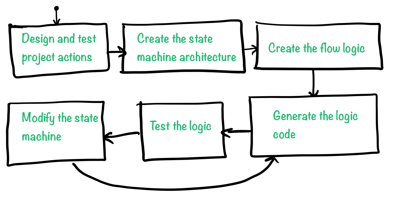
- Design and test the project actions. Actions are individual tasks that that should be done by the system. Something like, toggle a LED, send a byte over I2C, or perform signal conditioning on ADC samples.
- Based on the type of actions, decide how many different threads your application need. as a rule of thumb, try to group similar and inter dependent tasks into one thread.
- Based on your choice of architecture, design your state machine by adding serial or parallel states as well as transitions to each state machine.
- Generate the state machine code using the Weld code generator and integrate the code into your application.
- Test the generated code on the micro-controller system.
- Modify and repeat the last two steps as needed.
Threads and Multi-Threading
A thread is a small sequence of instructions that are executed one after another and are managed independently by a scheduler. The instructions that are present in one thread are executed sequentially, from start to end and there is no real way of starting from the beginning, once a thread starts executing its instructions (not in a practical sense at-least). Thread is the basic concept that gives the illusion of multi-tasking to an embedded software and helps divide the unrelated tasks that micro-controller should perform into different sub-programs.
We mentioned the illusion of multi-tasking or multi-threading because everything in (most) micro-controllers actually runs on a single physical CPU. Different threads are just executed one after another.
When developing with Weld, a thread is actually a single (possibly nested) state machine that executes some function(s) depending on input condition(s). Examples of threads in embedded development could be:
- Data Acquisition thread, that executes possibly after each ADC interrupt and reads the data from ADC buffers, runs signal conditioning algorithms and filters, and then loads the data to a user defined data buffer.
- Control Algorithm thread, that maybe, takes tha ADC data as the input, opens or closes some valves and send the data to a flash memory for logging propose.
There could be infinite number of threads in a program, but realistically, similar and dependent tasks should be grouped together as one thread in order to keep the complexity of the system down. As the number of threads grows, the overhead of managing them quickly makes a burden both to the developer and the limited resources of the micro-controller.
Thread Execution
Each thread is essentially a function that gets called and executed according to a schedule. There are multiple types of process schedulers that can be employed in embedded systems. Just to name a few here:
- Pre-emptive Scheduler, where tasks are scheduled according to their priority.
- Round-Robin Scheduler, is a fair scheduler, where task are executed one after another, within a pre-defined time slot, according to a pre-defined order.
As it is mentioned, there is only one CPU core available in each micro controller, so in order to execute several threads and achieve multi-threading, a scheduler should be employed to manage and divide the CPU time between several threads. Embedded Real-Time Operating Systems (RTOS) have been used to manage and schedule the CPU time. In spite of their effectiveness, RTOSes have several drawbacks:
- Steep learning curve
- Not available on all platforms
- Computational, RAM and Flash overhead in an already resource constrained system
- Difficult to debug
Using the Weld application to design and generate micro-controller threads, you can fit more functionality into a single thread (using nested state machines) which results in a lower number of threads. Round-robin scheduling can be easily achieved by placing the thread function calls, one after another in the main loop. Also, pre-emptive scheduling can be design using timer interrupts with different priorities.
Tip
The easiest and most effective type of scheduler is the timer interrupt. Timer interrupts allow for thread preemption as well as fixed frequency thread execution.
We suggest that you enable one timer interrupt per thread in your application and execute the thread functions inside the timer interrupt handlers.
States
States are building blocks of a state machine and since threads are state machines, states are building blocks of threads too. Each state represents represent a "state" that a thread could be in, and in each state, a thread could respond differently to the input variables and execute a different code (Action). An Action, is a snippet of code that gets executed in an state.
Note
There are three different types of Actions:
- Entry (en), are executed once, upon entry to a state
- During (du), are executed if a state is already entered and it is not being exited
- Exit (ex), are executed once, upon exiting a state
A thread moves between different states by evaluating Edges that are connected to the current active state.
Edges
Edges represent all the ways that a state machine can move from one state to another. Edges are evaluated in the execution cycle that follows after the entry to the state and if there is no valid edge to move the state machine from one state to another, the During actions of the active state are executed.