Finite-State Machine
A Finite-State Machine (FSM or a State Machine for short) is a computational model to simulate sequential logic or algorithms. The FSM can change the state of the system from one to another in response to some inputs and each state specifies which state to switch to in response to the input. A finite-state machine can be implemented using hardware (i.e. FPGA) or software (i.e C-code).
There are two types of state machines:
- Deterministic FSMs
- Non-Deterministic FSMs
In a non-deterministic finite state machine, the machine can move to any combination of states for each given input.
A finite-state machine is called a deterministic, if each of its transitions is uniquely determined by its source state and system input. In other words, Deterministic refers to the uniqueness of the computation run.
State-machines are so powerful and popular, that if you look closely around you, you can find a number of systems that employ them in their logic. One example can be turnstile in a subway, which can be represented by the following diagram.
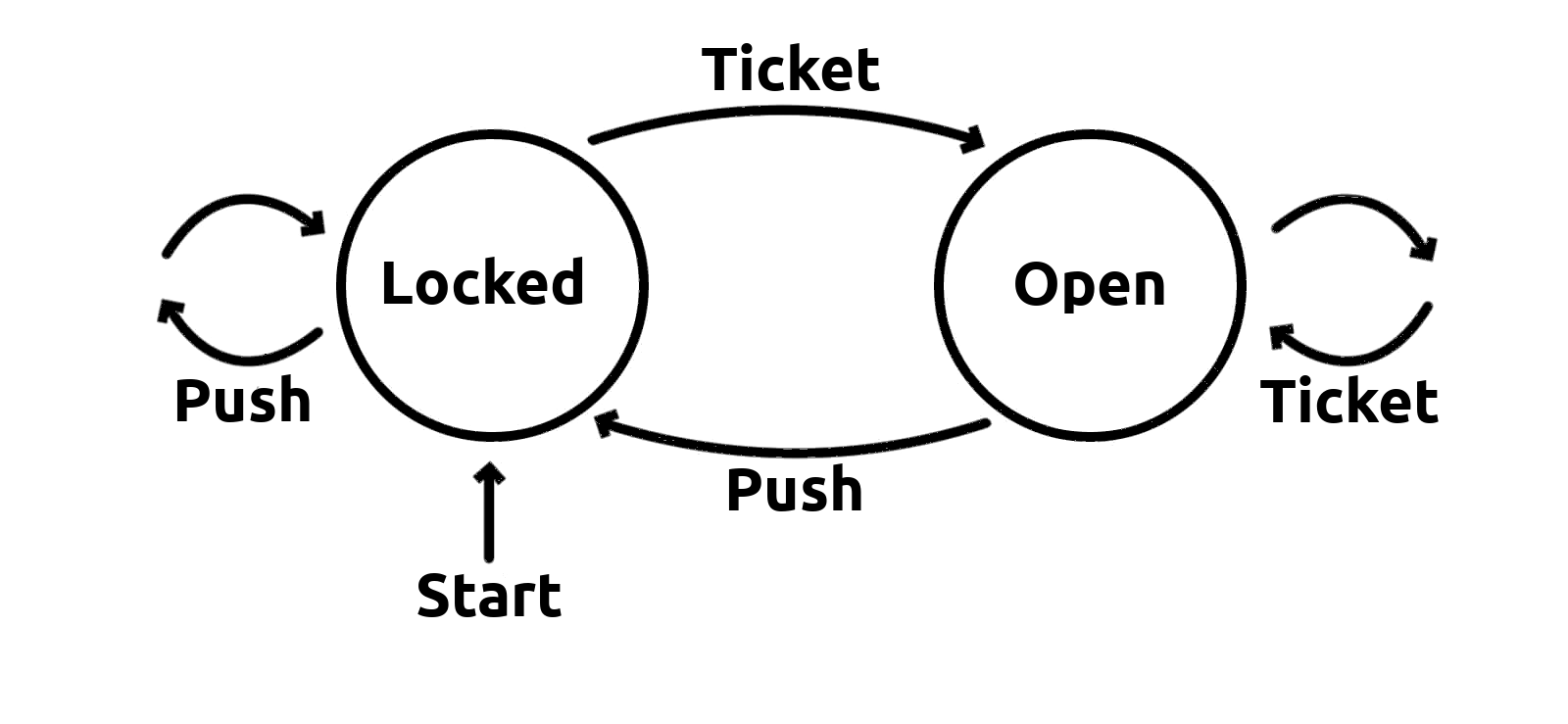
Using the Weld app, the above state-machine can be translated to:
1 2 3 4 5 6 7 8 9 10 11 12 13 14 15 16 17 18 19 | switch (state) {
case locked:
if (ticket) {
state = open;
} else {
state = locked;
}
break;
case open:
if (push) {
state = locked;
} else {
state = open;
}
break;
default:
state = locked;
break;
}
|
This is obviously a very simplistic example and as the state machine grows bigger, developing and managing its code logic becomes exponentially harder.
Representations
There are a number of ways for representing and visualizing a state-machines. For a simple machine, a State Transition Table would be the best option due to its simplicity and clarity. However, for more complex machines, this representation becomes impossible to use.
UML State Diagrams are best suited for representing state machines as they overcome limitations of transition tables and are able to represent the concepts of nested and parallel states.
Info
Weld uses UML State Diagrams to represent State Machines.
The Weld application uses UML State Diagrams to represent the Deterministic FSM that represents the logic of your code.
Using the UML representation, you can:
- specify a start transition to denote the initial state to be activated when the state machine executes for the first time
- create nested state machines and further divide the code logic and visually create complex decision trees
- add transition actions to execute code snippets for given conditions
These are just some of the benefits of UML representation. By using the Weld application you will be able to experience, first hand, how easy it is to create and maintain extremely complex code logic, and just how much functionalities tou can fit into a small controller.